Monday, December 30, 2013

Holiday Hacking Bender - Day 6 - Project 2


I've been thinking about this project for a long time.  Many years ago (mid to late nineties) I took a lot art classes just for fun.  I explored a lot of media including drawing, ceramics, photography (we used a thing called "film" back then), but my favorite was jewelry.  I did mostly fabrication, and specialized in lockets and other enclosures.  One enclosure I've always been fascinated by is the reliquary. I'm not sure of the Webster's definition, but I see them as a small secure places to keep something ancient and treasured.  Now, one of the things I've always held with that group of ancient and treasured objects are stones containing carved petroglyphs.  I'm thinking a stone bearing a personal totem encased in a wearable reliquary would be a brilliant piece of jewelry.

Jump forward to today, or at least the recent past, when I finish putting my ShapeOko together, and the first thing that occurs to me is "I wonder if I can get it to carve petroglyphs?".  Today's project is the beginning of that exploration. I don't want the glyphs to look machined, so I'm attempting to build a vibratory hammer type thing.  This version is a simple electromagnet with a hardened steel plunger retracted with a rubber band.  After playing with this today, I'm not sure I can get this design to go fast enough.  I might need to go to active position control of the plunger.  Right now the control circuit is a 555 driving a TIP120 - pretty simple.


Holiday Hacking Bender - Day 6 - Project 1


The first project of the day was pretty simple, but meant a lot.  A couple of months ago my son Nathan spent his allowance on a Raspberry Pi.  He mostly got it because he heard he could learn to program Minecraft on it, but he's also into Snap-Circuits, and other geek stuff, so for Christmas I got him a pi case, cobbler, and getting started book from Adafruit.  He also got his own soldering kit, so this morning I helped him through putting together his cobbler and getting his pi into the case.  The he wrote some python to make Das Blinken Lite Machine.


Holiday Hacking Bender - Day 5

Not Such a Good Day

I had planned another wood working project for the day, but couldn't stand the idea of doing it with the state my shop was in.  I spent a great deal of the day cleaning and organizing the shop, and ran out of energy before I got anything made.  Yes - things were quite the mess, and still not completely straight.  I need to build some tool cabinets before I'll be able to organize everything the way I'd like.  I will make up for the lapse by making two projects today, day six.

Saturday, December 28, 2013

Holiday Hacking Bender - Day 4


What you see is the result of today's efforts from the electronics department. Things went pretty well there, and I feel pretty good about the build. The brown board on the left is obviously an Arduino clone. I build the little "micro shield" to provide a robust plug in for an I2C interface. The little green board on the right holds an MLX90614ESF-AAA Infrared Temperature Sensor. It's connected to the micro shield with an upcycled USB cable, so the sensor can be some distance from the Arduino.  Right now it's just running an example sketch I shamelessly stole from bldr.blog.  Then, not being satisfied with stealing only a little I went out to an Australian Robotics site I found through ThingSpeak and stole some more code to post the temperature data to a channel on ThingSpeak.

So, the electronics department delivered, and the software department, after having been abused by assembly language programming all day yesterday, lost all sense of moral direction and stole everything, so in a way they delivered.  The manufacturing guys though, just couldn't pull it off today.  I had intended to build a desk lamp like articulated arm to hold the temperature sensor in varying places and orientations.  I got the design done, the g-code is even available, but my CNC just would not cut the parts.  After two attempts, each of which took more than an hour of cutting time. I decided to just give up.  I think the machine has a problem with static build up or is haunted, because on longer cuts it just intermittently looses its mind.

Anyway, that's all for day four, see you again tomorrow.

Friday, December 27, 2013

Holiday Hacking Bender - Day Three

Today was a lot more fun than yesterday.  I installed new sensors and software on my little red robot.  I read a definition for what a robot is the other day that I really liked more than any other definition I've ever heard.  The definition didn't have anything to do with technology or autonomy, it simply said that any machine with enough personality to be given it's own name is a robot.  I care for and watch over many small machines others might call robots, but only a select few have earned names.

I bought this red magician chassis just to see what a fifteen dollar robot chassis would look like.  I'm kind of stuck on the red now, and I keep tinkering with the little guy trying to coax something really endearing out of him.  I made some progress today, and with the new sensors opened some new paths for him.  Maybe someday he'll earn a name.


Thursday, December 26, 2013

Holiday Hacking Bender - Day 2

For today's project, I wanted to get up from my electronics desk, and get into the wood shop.  My wife has been asking for a jewelry box, so I decided to try to do it in a single day using a technique called a "band saw box".  This technique takes all the complex design and joinery out of building a box with drawers.  I drew my design free hand directly on the wood, then made all the cuts on my band saw, again free hand.
Even though it's a lot easier than flat panel construction, it's still wood working, and demands a certain precision.  I took some shortcuts here and there and paid for it later when I screwed up the bottom half of the box so badly I had to cut it off and throw it away.  Yes, the original design had four drawers.  I made the decision to take this drastic step about 5:00 pm this evening, and I was about ready to bag the whole project and call today a fail.  I'm glad I didn't give up, because even as it is the box brought a smile to my wife's face.  Although her first comment was "You do realize it's not big enough, right?"
Well, that's all for tonight.  Tomorrow I pick the soldering iron back up.


Wednesday, December 25, 2013

Holiday Hacking Bender - Day 1

Day one is almost over.  I got the last bit of code uploaded to the Arduino about 1/2 an hour ago, and now I'm documenting things a little bit.  Last year at this time I put together a simple Cheerlights nightlight, but it depended upon a PC, and ran mostly in Python.  A couple of months ago I purchased an ethernet shield, but never really did anything with it until today.  This afternoon I built up a dead simple low side BJT driver for a one meter non-addressable led strip, soldered some female headers into my ethernet shield so I could bread board with it, and mashed up the Arduino Ethernet Library Client example with my year old Cheerlights Python into ugly but working code.  Before the Bender is over I'll be building a fixture for the led strip and installing it outside as my house light.

Tuesday, December 24, 2013

Down with the funk

Since about the middle of the year I've been in a real maker slump.  It started with my day job really sucking the life out of me for a couple of months.  Now I'm struggling with a seasonally affected depressive episode.  I know making helps, but until recently I've lacked the energy and/or inspiration to get moving.

Well folks, today is my last day of work until January 6th 2014.  That gives me 12 days off in a row, with no plans to do nothing.  This post is my stake in the sand.  I will make, beginning to end, something new every one of those 12 days, and post about them as they are done.

I don't have a lot of ideas yet, so if you have a suggestion, please leave me a comment.  I think tomorrow I'll start by building a cheerlights display with the led string I recently got, an arduino, and a network shield.

Until tomorrow then - happy holidays.

Sunday, November 10, 2013

Flexibot 0.1 Update

Here's a short post to show the progress I've made on the flexibot development. I've been spending the majority of my time lately fixing things around the house, and haven't put a lot of effort into the project, but the first version is now what I'd call complete.

First off, I finished re-tooling the development platform by getting some little cable connectors made by Du-bro, cutting an adapter for an aluminum tubing leg on my ShapeOko, and making a terrible looking, but functional bent tubing leg.  The resulting robot has one active leg with two degrees of freedom, and demonstrates that a Sugru flexible link joint will support at least a little weight (this one is lifting four AAA ni-cad batteries) and is useful for walking.

I didn't edit the video down, so it's kind of long - sorry about that.  It does showcase most of what flexibot 0.1 can do right now.  I hope you enjoy, at least part of it.


Saturday, November 2, 2013

Drawbot 3.0 Makes Its Mark

I finally got the finishing touches on the new version of the Drawbot, and it drew its first images today.


I will be fully documenting the build, and perhaps offering boards and such.

Monday, October 21, 2013

Update on flexibot

A few days ago I cast two more flexible links for my flexibot development platform.  My initial link was a #1 SRFLG (standard RobotGrrl flexible link guage) - about 4 mm diameter.  The two new ones I cast are a #2 SRFLG - about 6 mm in diameter, and #3 SRFLG - about 7 mm in diameter.
After they cured, I started flexing them with my fingers, just to get a feel for the flexibility.  My #3 quietly failed.
Close inspection of the crack seems to indicate there was internal structure to the link, so the Sugru isn't homogeneous.  Either I didn't get the Sugru squished together well enough, or didn't let it cure long enough. Oh well.  I've made 4 links, and experienced 50% failure rate.  I guess I have something to learn about casting Sugru.

Now, on to the good part.  I put the first flexibot frame together really quickly, and without much planning.  So, I discovered that hot glue isn't real good at take-apart-and-put-back-together prototyping.  I went back to CAD, and modified the frame design to incorporate interchangeable link base plates.

Here you can see my #1 and #2 links on their plates...
Here's the new frame...
and the frame with a link installed, from the front...
and the back...
I haven't yet figured out how I'm going to attach the control cables (actually I'm using polyester thread originally designed to stitch sails together) and still make them interchangeable.

If you have any ideas, leave me a comment.  Thanks for reading.

Sunday, September 29, 2013

New Line of Research

One thing I've been thinking about for years, is flexible robots.  I'm a pretty good fabricator, but the precision  and complexity, required to make useful multi-degree of freedom joints (like your shoulder) has always seemed a little daunting, especially if you try to make them compact.

Some time ago Erin Kennedy, a brilliant, creative, visionary robot builder, and long distance friend posted a couple of tidbits on a tentacle mechanism she was pursuing.  The first iterations I saw were 3D printed parts connected with machine screws.  After seeing a video put out by the folks who make Sugru illustrating the use of 3D printed parts as molds to form Sugru parts, I suggested to Erin she try using Sugru as a flexible link between her 3D printed parts.  The folks from Sugru caught wind of the project, and donated some material to the cause, and Erin ran like mad, quickly bringing the idea into a working model.

Shortly after Erin worked out her design, she started offering 3D printed parts for sale.  I immediately placed an order, and was quickly rewarded with dozens of electric green and orange parts, direct from Erin's lab.


That night I cast a couple of links, and in the morning had one good one to start with.  The other one stuck in the mold, and tore coming out.  Once again, let me shout out to the folks who make Sugru, they sent me a donation as well, and I'm finally putting it to good use.


This weekend I used Sketch-up to design a framework, cut the parts on my ShapeOko, and TADA - Flexibot 0.1 is born.


Right now I've got the servos hooked up to an RC receiver, and I'm just driving it around with the joystick on my transmitter.  This is just the beginning, and once I get a little further on the mechanics, I'll turn it into a proper robot with autonomous control.

Saturday, May 25, 2013

Drawbot update, and ShapeOko's first real work

Last night I spent some time in SketchUp designing a pen carrier for the new drawbot.  This morning I exported all the parts to .dxf, pulled them into CamBam+, generated the gcode, and cut parts on the ShapeOko.  Here's the results.


Wednesday, May 8, 2013

My New Toy Takes its First Steps

About three weeks ago my wife bought me a really cool gift, and tonight my new ShapeOko CNC mill took made its first moves.  The crappy video is it running the ShapeOko "Hello World" job.


Saturday, May 4, 2013

Drawbot software on it's way

To paraphrase "Cool Hand Luke" - what we have here, is the ability to communicate!

In this video the comms board and the pen carrier board are connected up and working for the first time.  The comms board connects to my desktop via USB, and is connected to the pen carrier board via RS-485. When I send a command out the USB, you can see the transmit and receive LEDs flash, then the pen carrier board responds by changing the servo's position.

The protocol the boards are running over the 485 link is dead simple right now, and not capable of multi-drop communication.  So, the next step is to implement a new protocol.  The carrier board also only implements binary servo positions up, and down.  The new protocol will give the ability to send data through the link, so I can control how far up/down the pen is.  With this I'll be able to use brush tip markers, and vary the line thickness drawn by the 'bot.


Tuesday, April 30, 2013

Two boards built

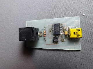
I've gotten two of the four boards for the drawbot built and sort-of working.  The top one is the controller for the pen carrier.  It will receive commands over the RS-485 bus (through the big black jack) and drive a servo through the 3-pin header.  The six pin header at the top is for in circuit programming the pic16f1823 micro, and the two pin header is for power.

The bottom board is the usb to RS-485 bridge I prototyped.  This version just has some indicator LEDs.  One for power and two more for data reception and transmission.

Now it's time to work on the software to get the two boards to talk back and forth. Oh happy happy joy joy!!


Monday, April 29, 2013

Green Boards Comin Outa Ma Ears

All my Drawbot boards arrived from the fabricator today.  Time to go by a bigger magnifier and get to building!

This is the communications board that converts USB to RS-485.


This is the board for the pen carrier.  It takes RS-485 in, and drives a servo to accomplish the pen up/down.


And this is the winch board.  It takes RS-485 in, and drives a 2 phase bi-polar stepper motor.


Thursday, April 25, 2013

Yet Another Particle-Bot Prototype

Here's another Particle-Bot prototype.  This one is a lot closer to how I see the final robot.  Using pager motors without a gearbox really cuts down on the unit cost, but to really be able to evaluate the design I need to build a better chassis.  I'm currently thinking 3D printing would be a good choice.


Two Particle-Bots, and two programmers, two nights work.


Tuesday, April 23, 2013

Another particle-bot prototype

Well, I couldn't wait to get a real chassis for my new Particle-Bot boards, so in about 20 minutes I put together this prototype - made form really cool purple cardboard.  


Here's a really crappy video of the 'bot programmed for light seaking


Monday, April 22, 2013

Particle-Bot boards delivered

One of my favorite books of all time is Vehicles: Experiments in Synthetic Psychology by Valentino Braitenberg.  It describes a series of robots controlled using small networks of synthetic neurons, and how  with just a few neurons very complex behaviors can emerge.  Complex enough in fact to be ascribed anthropomorphic labels such as fear, shyness, and indecision.  This book is the inspiration for my latest robot, somewhat appropriately named Particle-bot because it's small, and I happen to like the group They Might be Giants, and their song Particle Man.

This is a shot of the prototype Particle-Bot.  It's built with small gear motors, a small Li-Po battery, and boards I fabricated and built up.  The chip is an ATTiny85 processor, so the software is written using the Arduino IDE, and it programmed using an Arduino with minimal supporting circuitry, and software from here.


After getting the prototype up and going, I refined the board layout, added some other bits, and sent the boards here to get them commercially produced.  The Eagle files for the board are available here.  Today the boards arrived in the mail - YEAH!!

Here's a shot of the front & back of the board.  The maximum size for the boards in the order I made was two inches by two inches.  Because Particle-Bot is so small, I was able to fit the main board, and the "eye stalks", as well as two other boards that implement the ATTiny programming circuit for the Arduino.


Here's the boards cut apart into the the five pieces.  I used my jeweler's saw to cut them apart, and I'm not too great at straight lines with it, but you get the idea. The sixth piece (the thinnest) is waste.


So here's a picture all the boards built up, ready to go to work. The two boards connected together with the twisted wires are the programming circuit.


And this is how it fits on top of an Arduino Duemilenove clone.  I'll be working on a tutorial on how to setup and use the programmer real soon now.


I'm still working on a design so the chassis of the robot can be 3D printed, so seeing the 'bot completely built out and running will have to wait until that's done.

Wednesday, March 27, 2013

Stella with style

I had to put down the drawbot project for a bit, so I put some time into Stella this evening.  One of the things I want to do is somehow make the web cam on Stella's head less obvious, and more part of the brrd.
So tonight I worked up a quick prototype of an idea I've been thinking about.  With some cardboard, hot glue, masking tape, and rigid foam I made a crest.  If I decide to go this route, I'll be making the real one out of sewn fleece stuffed with polyfill.  If I get ambitious I may even put a servo inside and make it move.
Please leave me a comment to let me know how you like (or don't like) the crest.

Sunday, March 24, 2013

Drawbot Design Files Released

I have released the drawbot 3 design files on Google drive.  There are Eagle schematic and board files, as well as the Gerber files I'll be sending in for fabrication.


The Comms board has been prototyped and I know works.  The other two have not yet been built up, so who knows at this point.  Enjoy.

Wednesday, March 20, 2013

Drawbot USB to RS-485 converter up and running

I found out soldering .025 pitch leads is pretty tough.  I let the magic smoke out of one FTDI chip before I really figured out how to do it.  This evening I found the last bugs, and now it's up and running.  Using the frequency counter feature of my meter I can tell the output changes when I send in data over USB, but I don't have any RS-485 devices right now to check if the data is any good.  I guess that's the next task before I send the boards out for fab.


Saturday, March 16, 2013

Drawbot 3 New tools and new board

Here's a snap of my new soldering tools.  Iron, tweezers, flux, tip cleaner, helping hands, solder holder I built.  The iron has .012 inch tip I need to do .025 inch leads.
Here's a build up of the USB to RS-485 board.  The first real surface mount board I've built.  It took some time, but wasn't as tough as I thought it would be.

Wednesday, March 13, 2013

Drawbot 3 is underway

Well, I've got all the boards designed, and all the last of the parts arrived today from Digi-Key.  Now I'm starting the actual build by etching the first board.  This is a USB to RS-485 converter, and will provide my laptop with an RS-485 bus.  Tomorrow I go buy a new soldering iron, and some damn sharp tweezers.
I need to say thanks to Smallbox and Angie's List for the $1000.00 Nice Grant that makes this all possible.